News about World of Card Games, the website for card players who love Spades, Hearts, Euchre, Gin Rummy, Double Deck Pinochle, Twenty-Nine, 3-5-8 (aka Sergeant Major), and Go Fish!
Get news about updates on Facebook, and Twitter.
This is a somewhat different blog post from what you usually see on World of Card Games. It's part of a hobby project I've been working on for a while. I'm very interested in card games and programming, which is why I created the solitaire site Online Solitaire and now run World of Card Games. Besides programming and card games, I'm very interested in robotics, so I thought, why not try to create a robot and get it to play Peg Solitaire?
It proved to be somewhat of a challenge for a novice like me, but in the end, I managed to design, create, and program a delta-robot from scratch. So without further ado, let me introduce Peggy, the Peg-solitaire playing delta-robot:
A lot of creativity, calculations, dimensioning, prototyping and programming has gone into creating this robot. This blog post is part of a series of blog posts where we'll dive into different aspects of the robot. I've previously gone through how to do the kinematic calculations for a delta-robot, and in this post, we'll go through how to do the dimensioning, along with the calculations, for the capstan gear that is used in the robot.
When to use a capstan gear
There are many different types of gears, each with their own advantages and disadvantages. A well-known gear within the world of robotics is the pulley and belt system. This type of system works very well and is used in many different types of robotic design. The drawback of this type of system is that it usually has a certain amount of backlash. In a delta robot, where speed and precision are important factors, it is important that there is as little backlash as possible. That's why I decided to use a capstan gear. This type of gear is currently not very popular in the world of robotics but is finding its way into various projects like this robot dog.
As seen in image 1 below, the capstan gear works by having a motor move the capstan, which in turn moves the wheel it's connected to via a wire. The ratio between the capstan and the wheel determines the gear ratio.
Figure 1: An example of a capstan gearing
Dimensioning the capstan gear
In image 2 below, an illustration of a capstan gear with its associated dimensions is shown. The upper part is the capstan, in which the input shaft is mounted, the lower part is called the wheel, in which the output shaft is mounted, and both are connected by a wire that transfers the rotational forces from one wheel to the other.
To make the gear work correctly, the capstan and the wheel have to be dimensioned correctly. The calculations for the capstan gear used in this project have been deduced from a lecture from Stanford University and a graduation project from DTU (Technological University of Denmark). Below we'll go through these calculations to give you an idea of what's required if you want to create a capstan gear for your own project.
Figure 2: Illustration of the capstan gearing seen from the front and the side.
We have the following definitions:
\(\lambda =\) Angle of the wire. Also called the helix angle.
\(S =\) Pitch of the wire.
\(D_{C} =\) Diameter of the capstan.
\(D_{O} =\) Diameter of the wheel.
\(L_{G} =\) Distance between capstan and wheel.
\(S_{O} =\) Pitch of the steel wire on the output shaft.
\(D_{W} =\) Diameter of the wire.
Doing these calculations, we're really looking to deduce three main numbers: how thick the wire should be to withstand the motor's torque, how many times it should be wound around the capstan so that there is enough friction to prevent slippage, and how large the pitch of the wire should be to prevent too much pressure on the capstan or wheel when the wire travels. Based on these numbers, the minimum width of the capstan and wheel is found.
An important factor in these calculations is the helix angle, \(\lambda\), as it must be kept constant across the capstan and wheel to prevent stresses in the gear. Thus, the following relationship is given:
The distance \(L_{G}\) should be as small as possible to avoid unnecessary tensile forces on the capstan and wheel. In an ideal world, the distance would be no greater than the wire diameter, i.e., \(L_{G}=D_{W}\), but to ensure that the wire doesn't get squeezed between the capstan and the wheel, the distance is set to \(L_{G}=1.5 \cdot D_{W}\). This would result in very few tensile forces in the vertical plane on the capstan and wheel.
Diameter of the wire, the capstan, and the wheel
The wire's main job is to transfer the torque from the capstan to the wheel. This is done exclusively using a tensile force. The torque can be found using the definition for torque:
\begin{align}torque &= force \cdot arm \\M &= F_{W} \cdot \left(\dfrac {D_{C}}{2} + \dfrac {D_{W}}{2}\right)\end{align}
Where \(M\) is the torque from the motor and \(F_{W}\) is the tensile force. By re-structuring the definitions, the tensile force can be determined as:
Before the tensile force can be found, the diameter of the capstan and wheel must first be determined. There are some practical considerations to take into account when dimensioning the gear. A capstan gear physically takes up a relatively large amount of space. The larger the gearing, the larger the robot will have to be. I've decided to have a gear ratio of 1:8, as this seems large enough to achieve the desired precision while the robot can maintain the desired speed.
The second thing you should consider is that the capstan's diameter contributes to how much tension is in the steel wire. For a standard 7x7 wire, it is recommended that the capstan's diameter should be at least 16 times larger than the diameter of the wire. With a gearing of 1:8, the wheel should be 8 times larger than the capstan.
We'll try with a 1mm wire to see what safety factor we'll get:
Using the above dimensions, the wire will have a safety factor of almost 4, which is fully acceptable for a robot like this.
Number of wraps around the capstan
For the torque to be transferred from the capstan to the wheel, the wire should be wrapped around the capstan enough times so that it does not slip. The number of times needed is found using the capstan formula which is:
The wire force is found to be \(F_{W} = 143N\), and the static friction coefficient is estimated to be \(\mu_{static} = 0.2\)\cite{frictionCoefficient}. The holding force is now found for different number of wraps:
It's clear that there is a significant difference in how big the holding force should be in relation to the number of wraps around the capstan. To have as large a safety factor as possible regarding whether the wire slips, the last calculation is chosen, i.e., the wire is wrapped around the capstan four times.
The width of the capstan and the wheel
The only thing left to determine is the capstan and wheel width. The previous calculations form the basis for this width. As shown in image 3 below, we're looking to find \(B_{min}\), which is the minimum width for the wheel. It should be noted that, in practice, a little extra width should be added.
Figure 3: Width of the capstan gearing.
The minimum width is a function of the minimum distance for the wire on the capstan, \(B_{C}\), and the width of the wire that wraps around the wheel, \(B_{O}\). The minimum width for the capstan can thus be found by:
\begin{align}B_{C} &= N \cdot S\end{align}
The width \(B_{O}\) depends on the anchor point placement on the wheel (the x's in image 3), \(\beta\), which depends on the desired rotation of the wire on the wheel, \(\alpha\):
The distance \(L_{G}\), i.e., the distance between the capstan and the wheel, has been determined to be so small that it can be ignored in this calculation. The minimum width for the gearing can thus be found to be
If we set the distance between the wires to be \(S = 2mm\), and the number of wraps to be \(N = 4\), \(\alpha = 1.2\pi\), and \(\beta = 0.1\pi\), we get:
The minimum distance for the wheel can therefore be determined to be 18.8mm. In practice, it will be wider, but now we know that this is the minimum distance.
The prototype
Dimensioning something is not much fun if you don't get to create a prototype of it, which is exactly what I've done! 🙂
There are many different ways to design a capstan gear and even more production techniques one can use to create it. I've chosen 3D-printing and laser-cutting as my production techniques. In image 4 below, the prototype of the capstan gear is shown. It has been produced in clear plastic so that all details can be seen. The upper arm is held in place by a shaft that is connected to 2 608RS ball bearings, ensuring as little friction as possible. A spacer has been placed in the middle of where the upper arm sits. This has created more stability between the suspension and the upper arm.
Figure 4: The prototype of the capstan gear.
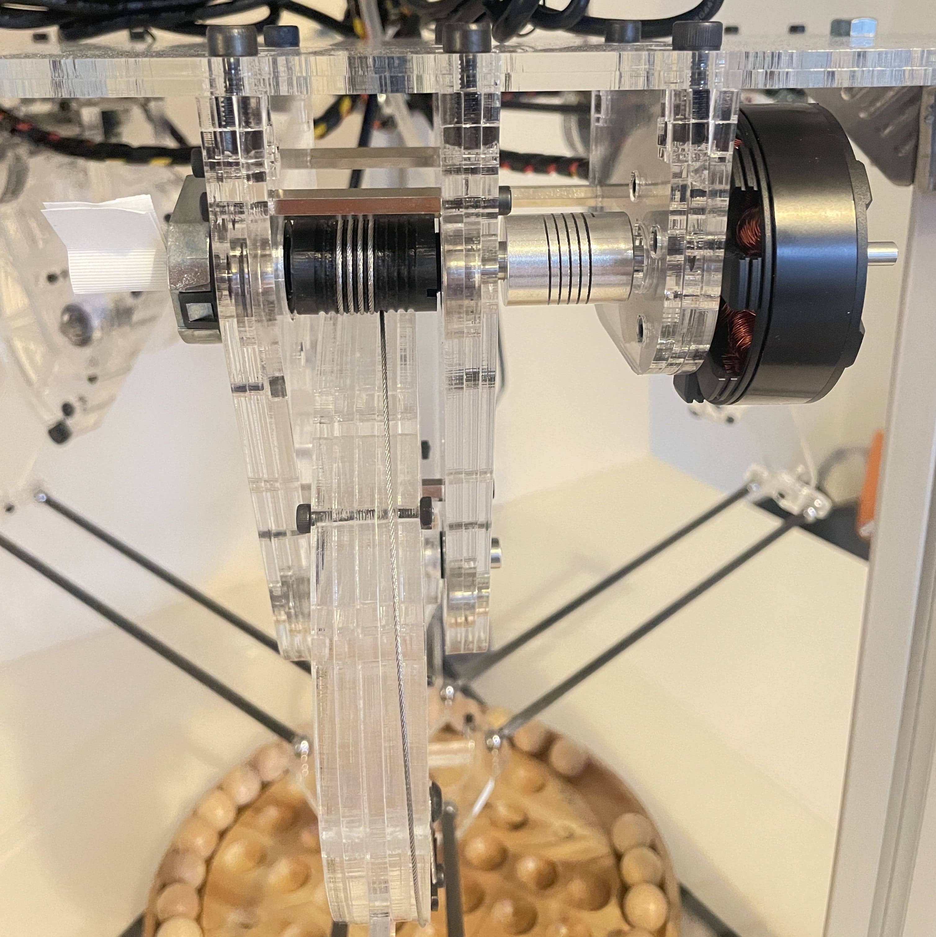
In image 5, the capstan gear and upper arm are shown. This shaft is clamped to the motor through a flexible coupling. This couple has been chosen because we cannot guarantee that the shaft and motor shaft are perfectly aligned. In addition, the shaft extends through to the encoder on the left, which it, in turn, is connected to.
Image 5: Capstan and wheel.
That's all for now. I expect to write up a few more posts in the future with some of the interesting aspects of the robot. Let me know in the comments if you have any questions.
.jpg)
.jpg)
.jpg)